CPT-CAD

Geological cross section and geotechnical cross section can be made in the CPT-CAD program. It contains a set of tools enabling automatic generation of geological and geotechnical cross sections and maps based on information contained in interpreted CPTU soundings and information contained in the geological and geotechnical database GEO DB.
CAD graphics
The implemented CAD-type graphics enable the creation of this documentation in the DWG and DXF format and the editing of DWG and DXF files created in other programs.
The structure of drawing layers is fully compatible with the structure implemented in CAD programs (e.g. AutoCAD). This option significantly facilitates the creation and editing of drawings, especially sections and maps.
The CPT-CAD module, thanks to its implemented graphic functions, is an excellent tool for creating maps with the location of drill holes, CPT tests and other tests. Thanks to full compatibility with DXF files, a standard terrain map generated in AutoCAD or Microstation can be used as the background of this map.
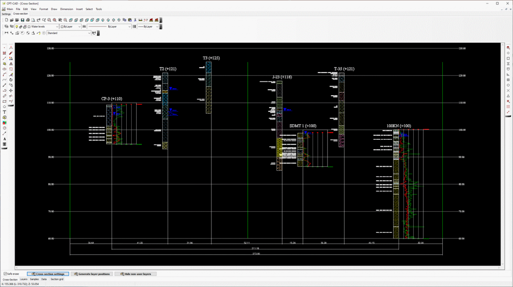
Contents of cross-section
The cross-section contains, among others:
▪ Borehole profiles filled with hatching or colors from the interpretation of CPTU soundings
▪ Borehole profiles filled with hatching or colors from the GEO DB database
▪ Division into geological and engineering layers
▪ Descriptions of soil types
▪ Characteristics of layers and parameter values saved in GEO DB
▪ Groundwater level symbols
▪ Distances between boreholes
▪ Elevations of the roof and floor and thickness of layers
▪ Graphs of parameters saved in GEO DB
▪ Graphs of CPT, DMT and DPT soundings
▪ Vertical and horizontal grid of the cross-section
▪ Grids for individual graphs